Introduction
The “Overhead Tank Water Level Detection and Overflow Control System” is an innovative solution designed to monitor water levels in overhead tanks and prevent overflow. By utilizing a microcontroller (ESP8266), carbon sensors, and various other components, this system provides real-time water level information and automatically controls the water pump to conserve water and energy. This project is crucial for households and industries where water management is a priority, offering both convenience and sustainability.
Features of the System
- Real-time Water Level Indication: The system displays the current water level of the tank using a series of RGB LEDs. Each LED represents a specific water level percentage, allowing users to visualize the tank’s status at a glance.
- Automatic Pump Control: The system automatically turns off the water pump when the tank is full, preventing water wastage due to overflow. This feature also reduces the manual effort required to monitor and control the water pump.
- Waterflow Detection: The system includes a feature to detect whether water is actually being pumped into the tank. If water is flowing into the tank, the topmost LED will blink blue. If no water is detected, the LED remains off, alerting the user to potential issues.
- Low Power Consumption: The system is designed to be energy-efficient, consuming less than 1 watt in idle condition. At peak load, when the tank is full and the system is fully operational, the power consumption rises to around 2 watts.
- User Alert System: When the tank is full, the system not only turns off the pump but also activates a buzzer to alert the user. This ensures that the manual switch controlling the pump can be turned off, preventing unnecessary power usage.
- Robust and Reliable Design: The use of carbon sensors, coupled with the ULN2003 Darlington pair IC and PISO shift register, provides a reliable method for detecting water levels. The system balances the accuracy of digital sensors with the robustness of mechanical systems, offering a durable solution that requires minimal maintenance.
Components Used
| Component | Quantity |
|---|---|
| ESP-12E (ESP8266) Microcontroller | 1 pcs |
| Carbon Sensors | 8 pcs |
| WS2811 RGB LED | 7 pcs |
| 5V Buzzer | 1 pcs |
| 5V 1A SMPS | 1 pcs |
| ULN2003 IC | 1 pcs |
| 74HC165 PISO Shift Register | 1 pcs |
| 3 Pin Terminal Connector | 3 pcs |
| 2 Pin Terminal Connector | 2 pcs |
| 1K ohm Resistor | 10 pcs |
| 10K ohm Resistor | 1 pcs |
| BC547 Transistor | 1 pcs |
| 5mm Green LED | 1 pcs |
| 16 Pin IC Base | 2 pcs |
| Veroboard | 1 pcs |
| 1N4007 Diode | 1 pcs |
| Connecting Wire | – |
| AMS117 3.3V Regulator | 1 pcs |
| 5V Sugar Cube Relay | 1 pcs |
| Male & Female Header | 32 pcs |
Circuit Diagram

Theory & Working of the Circuit
The system works by using carbon sensors that detect the water level in the tank. These sensors are connected to the ULN2003 Darlington pair IC, which amplifies the small signals from the sensors and sends them to the 74HC165 PISO shift register. The shift register converts these signals into data that the ESP8266 microcontroller can process.
The microcontroller then interprets the water level data and controls the RGB LEDs to indicate the current water level visually. The LEDs light up in different colors depending on the water level:
- Red: Low water level (0-25%)
- Yellow: Medium water level (26-50%)
- Green: High water level (51-100%)
- Blue (Blinking): Indicates that water is currently flowing into the tank.
When the water reaches the top of the tank, the system turns on the relay to cut off the pump’s power supply, preventing overflow. Simultaneously, the buzzer is activated to alert the user to manually turn off the pump. This feature ensures that the system is not only automated but also user-interactive, providing both convenience and control.
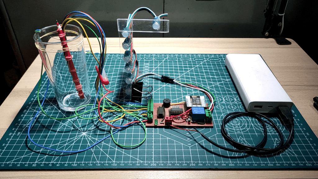
Prototype Build
Prototype Circuit


Carbon Sensors


The Whole System


Tracks & Soldering

Schematics of PCB

PCB Layout Images


Photo View of the PCB


Code for the Project
#include <FastLED.h>

#define NUM_LEDS 7    // Number of LEDs in the strip
#define LED_PIN 5     // Pin where the LED strip is connected

// Create an array to hold the data for the LEDs
CRGB leds[NUM_LEDS];

// Define pin connections for the shift register
const int dataPin = 12;   // Data pin for reading from the shift register (Q7)
const int clockPin = 13;  // Clock pin for shifting bits (CP)
const int latchPin = 14;  // Latch pin for updating the shift register (PL)

// Number of bits to read (8 bits for 1 shift register)
const int numBits = 8;

// Array to hold the binary data read from the shift register
int a[8];

// Function prototype for converting binary array to decimal
int BinaryToDecimal(int a[]);

// Variable to store the decimal value converted from binary
int check;

// Define pin connections for the relay and buzzer
int relayPin = 4;    // Pin connected to the relay
int buzzer = 16;     // Pin connected to the buzzer

void setup() {
  Serial.begin(115200);  // Initialize serial communication for debugging

  // Set pin modes for the shift register
  pinMode(dataPin, INPUT);
  pinMode(clockPin, OUTPUT);
  pinMode(latchPin, OUTPUT);

  // Initialize the FastLED library and set the brightness of the LEDs
  FastLED.addLeds<WS2811, LED_PIN, RGB>(leds, NUM_LEDS);
  FastLED.setBrightness(60);

  // Set pin modes for the relay and buzzer
  pinMode(relayPin, OUTPUT);
  pinMode(buzzer, OUTPUT);
}

void loop() {
  // Step 1: Sample the shift register
  digitalWrite(latchPin, LOW);   // Pull latch pin low to prepare for data capture
  digitalWrite(latchPin, HIGH);  // Pull latch pin high to capture data from the shift register

  // Step 2: Shift out the bits from the shift register
  int j = 0;  // Index for array to store binary data
  Serial.print("Bits: ");
  for (int i = 0; i < numBits; i++) {
    int bit = digitalRead(dataPin);  // Read each bit from the data pin
    if (bit == HIGH) {
      Serial.print("1");  // Print 1 if the bit is high
    } else {
      Serial.print("0");  // Print 0 if the bit is low
    }
    a[j] = bit;  // Store the bit in the array
    j++;

    digitalWrite(clockPin, HIGH); // Shift out the next bit
    digitalWrite(clockPin, LOW);
  }

  // Convert the binary array to decimal and process the result
  BinaryToDecimal(a);

  Serial.println();

  // Blink the last LED if water level is high
  if ((check == 64) || (check == 65) || (check == 67) || (check == 71) || (check == 79) || (check == 95) || (check == 127)) {
    leds[6] = CRGB::Blue;    // Set the last LED to blue
    FastLED.show();          // Update the LEDs
    delay(200);              // Wait for 200 milliseconds
    leds[6] = CRGB::Black;   // Turn off the last LED
    FastLED.show();          // Update the LEDs
    delay(200);              // Wait for 200 milliseconds
  }
}

int BinaryToDecimal(int a[]) {
  int sum = 0;   // Initialize the sum to 0
  int mul = 128; // Initial multiplier for the highest bit (2^7)
  for (int i = 0; i < 8; i++) {
    if (a[i] == 1) {  // If the bit is 1, add the multiplier to the sum
      sum += mul;
    }
    mul /= 2;  // Divide the multiplier by 2 for the next bit
  }
  Serial.println();
  Serial.print("DEC: ");
  Serial.print(sum);  // Print the decimal value
  check = sum;        // Store the decimal value in the check variable

  // Update LEDs and control relay and buzzer based on the water level
  switch (sum) {
    case 1:
    case 65:
      // If the water level is low, turn on the first LED and turn off others
      leds[0] = CRGB::Red;
      leds[1] = CRGB::Black;
      leds[2] = CRGB::Black;
      leds[3] = CRGB::Black;
      leds[4] = CRGB::Black;
      leds[5] = CRGB::Black;
      FastLED.show();  // Update the LEDs
      break;
    case 3:
    case 67:
      // If the water level is low to moderate, turn on the first two LEDs
      leds[0] = CRGB::Red;
      leds[1] = CRGB::Red;
      leds[2] = CRGB::Black;
      leds[3] = CRGB::Black;
      leds[4] = CRGB::Black;
      leds[5] = CRGB::Black;
      FastLED.show();  // Update the LEDs
      break;
    case 7:
    case 71:
      // If the water level is moderate, turn on the first three LEDs
      leds[0] = CRGB::Yellow;
      leds[1] = CRGB::Yellow;
      leds[2] = CRGB::Yellow;
      leds[3] = CRGB::Black;
      leds[4] = CRGB::Black;
      leds[5] = CRGB::Black;
      FastLED.show();  // Update the LEDs
      break;
    case 15:
    case 79:
      // If the water level is moderate to high, turn on the first four LEDs
      leds[0] = CRGB::Yellow;
      leds[1] = CRGB::Yellow;
      leds[2] = CRGB::Yellow;
      leds[3] = CRGB::Yellow;
      leds[4] = CRGB::Black;
      leds[5] = CRGB::Black;
      FastLED.show();          // Update the LEDs
      digitalWrite(relayPin, LOW); // Turn off the pump
      digitalWrite(buzzer, LOW);   // Turn off the buzzer
      break;
    case 31:
    case 95:
      // If the water level is high, turn on the first five LEDs
      leds[0] = CRGB::Green;
      leds[1] = CRGB::Green;
      leds[2] = CRGB::Green;
      leds[3] = CRGB::Green;
      leds[4] = CRGB::Green;
      leds[5] = CRGB::Black;
      FastLED.show();  // Update the LEDs
      break;
    case 63:
    case 127:
      // If the water level is very high, turn on all six LEDs
      leds[0] = CRGB::Green;
      leds[1] = CRGB::Green;
      leds[2] = CRGB::Green;
      leds[3] = CRGB::Green;
      leds[4] = CRGB::Green;
      leds[5] = CRGB::Green;
      FastLED.show();          // Update the LEDs
      digitalWrite(relayPin, HIGH); // Turn on the pump
      digitalWrite(buzzer, HIGH);   // Turn on the buzzer
      break;
    default:
      // If the water level is unknown, turn off all LEDs
      leds[0] = CRGB::Black;
      leds[1] = CRGB::Black;
      leds[2] = CRGB::Black;
      leds[3] = CRGB::Black;
      leds[4] = CRGB::Black;
      leds[5] = CRGB::Black;
      FastLED.show();  // Update the LEDs
      break;
  }
  return 0;
}